Short Circuit Test of Transformer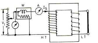
While a transformer short circuit the other hand ammeters watt meter and voltmeter with Connected to supply transformer short circuit test is that the test will be called. The transformer equivalent Resistance, impedance evaluate and determine the copper loss is short-circuit test.
Tested for transformer short circuit coils full load current to flow in the equivalent electrical outlets.
Tested for transformer short circuit transformer and low - voltage of the circuit is short because of the -
1. Less than the full load current of high voltage electrical outlets are used for low rang ammeters and watt meters.
The. Supply only 4% of the rated voltage is 10% of the supply is not a problem.
3. It is the correct voltage for full load outlets.
Transformers short circuit test method is described
Normally the transformer and low - voltage short circuit in the high voltage side of the meter and the watt meter ammeters volts is connected to the supply. Variable voltage supply source or from the series resistance 2% of rated voltage connection of the supply voltage with a gradual increase in the full-load current to flow until the transformer. High voltage to low voltage at full load current to flow when a particular certificate will not be short of the full load current to flow. The ammeters watt meter and volts meters are read into the record.
Received watt meter reading = Psc
Ammeter text = Isc
And voltmeter readings = Esc
Psc = transformer copper loss,
Re = Psc / I ² sc
Ze = Esc / Isc
Xe = √ Z ² e - √ R ² e
Mentioned that, for Re, Ze and Xe equivalent to the value of the high voltage.
Transformer short circuit test is when you are careful.
1. Transformer low fat side of the terminal, in short by resistance .
The. High side of transformer and the appropriate ratings -'s watt-meter, Volt meter, you will ammeter connection.
3. Ammeter range of outlets than the little ones to be loaded.
4. Transformer and voltage rating in volts meters range is about 10%.
5. 4% or 10% of the high-side voltage is applied. The voltage It is so full load current flow is ammeter.
The low core loss is needed voltage is inconsiderable.
Both coil full load current is flowing because this is the time to get Transformer that it accepts full load copper loss.

For example of mathematics
1. A 100 KVA 2400/240 V distribution Transformer short circuit test results are as follows -
Esc = 60 V, Isc = 34.67 A, Psc = 819.4 W transformer full load copper loss determined now.
Answer: -
Transformer IFL = 100,000 / 2400 = 41.6 A
Isc = 41.6 A.
Here,
I'sc = 34.67 A
P'sc = 819.4 W
Psc = (Isc / I'sc) ² × 819.4
= 1180 Watt.
2. A 100 KVA 2400/240 V distribution Transformer short circuit test results are as follows -
Esc = 60 V, Isc = 34.67 A, Psc = 819.4 W load, the transformer
1. 125 KVA,
2. 75 KVA
3. 0.772 power factor 85 KW to determine if each of the copper loss.
Answer: -
Transformer IFL = 100 × 1000/2400 = 41.6 A
Full load copper loss Psc = 1180A.
Here,
1. PscL = (125/100) ² × 1180 = 1845 W
2. PscL = (75/100) ² × 1180 = 663 W
3. KVAL = 85 / 0.772
= 1180 Watt.
PscL = (85/100 × 0.772) ² × 1180 = 1430 W

