শনিবার, ১২ মে, ২০১২

Effect of Sag Part:- 02


  It was learned that the key effect sag? We know that  mutual spacing of the conductive  and Span Length: -
Interval must be sufficient so that the overhead lines of mutual conductive  All side of  air and air ayounized insulation  can not break down. 
The distance between two conductive to the two sources are used. 
. Mutual interval = (0.01Vkv + 1.24D / W √ d) feet ............... (i) 
Where, 
Vkv = Voltage (kv) 
D = conductor diameter (inch) 
W = weight per unit length of conductor (ft) 
d = sag (ft) 

. Mutual interval = (0.075 √ d + Vkv ² / 20000) meters .................. (ii) 
. Where d = sag (meters) 
          Overhead line conductor of the different types of mutual minimum distance of the voltage. 
A list is given. 
Operating voltage
Vertical spacing
Horizontal spacing
Spacing between conductor & support
400/300 V
46 cm
38 cm
15 cm
11 KV
76cm
115 cm
31 cm
22 KV
91cm
137 cm
46 cm
33 KV
122cm
153 cm
61 cm
66 KV
200cm
325 cm
76 cm
110 KV
315cm
495 cm
110 cm
132 KV
370cm
590 cm
130 cm
230 KV
645cm
1028 cm
226 cm

If it is possible to create low-cost Transmission lines may be useful. The maximum limit for the line span (optimum) to be. The support  and Fixture such as the number of Insulator decreases, the cost will be lower. However, due to the increase in October sag support  height will increase, while the conductor spacing, increasing cross - arm's length will increase. Span length of the line to create a way to control costs should be increased, and the other kit is a high cost. 
Below the economic optimum span Powered_by_gitorious (most economical span length) and a different type and height of the support line and  voltage sag and span of the Table: - 
  
Line voltage (Voltage)
Type of support(Meters)
Hight of supports (Meters)
Approx. Sag
(Meters)
Approx. Span
(meters)
400/300 V
Wooden,concrete,tubular
8.5-9.0
0.5-1.0
50-70
11000 V
Tubular, rail
9-10
1.0-1.5
80-120
33000 V
Rail pole
10-12
1.4-1.8
110-130
66000 V
Tower
20-25
2.0-3.0
180-240
132000 V
Do
25-30
4.5-6.0
250-350
2220000 V
Do
30-40
7.0-9.0
300-400
380000 V
Do
35-45
8.0-10
350-430


Notes:1. - An overhead line span 200m. Conductor cable cross 3cm ² meters and weight of 0.85kg. 2000 kg per cm ² and a safety factor of 2 when the maximum meaningful tension wire sag calculate tax? 
Ans: - here, 
    m = 220 m, A = 2cm ², W / m = 0.85 kg. 
The maximum meaningful tension = 2000 kg / cm ², safety factor = 2 
d =? 
We know, meaningful tenasana = maximum strength (strain) × cross / Safety Factor 
                T = 2000kg/cm ² × 3 cm ² / 2 
                          = 3000 kg 
               Sag d = Wm ² / 8T 
                     Ans. = 0.85 × (200) ² / 8 × 3000 = 1.71 m. 
Notes: 2 - a river on a transmission line to the water surface and 30 m height, with the help of two tower has been constructed. Horizontal distance between towers 300 m. If the maximum strain carrying weight of 1590 kg and 0.8 kg All meters is, but how much above the river between the water surface may be conductive? 
Ans: - P1 = 30 m, P2 = 40 m 
T = 1590 kg, W / m = 0.8 kg 
h = P1-P2 = 10 m 
m = 300 m, H =? 
Now, 
 X1 = m / 2 - Th / Wm 
     = 300/2 - 1590 × 10 / 0.8 × 300 = 83.75 m. 
X2 = m / 2 + Th / Wm 
  = 300/2 + 1590 × 10 / 0.8 × 300 = 216.25 m. 
X = m / 2-X1 
  = 150 - 83.75 = 66.25 m 
d = W X ² 2/2T = 0.8 × (66.25) ² / 2 × 1590 = 1.1 m. 
d2 = W X ² 2/2T = 0.8 × (216.25) ² / 2 × 1590 = 11.76 m 
 H = P2 - d2 + d = 40 - 11.76 +1.1 
                        Ans = 29.34 m. 

Some Question and answer.
Tips: - 1. How many and what size sag? 
Ans = There are three different ways, namely: - 
1. Sag board  method. 
 2. Dynamo meter method 
3. Stop watch or return wave method. 
Tips: - 2. There are two common species to carrying out the distance between you? 
Ans = Mutual interval = (0.75 √ d + Vkv ² / 20000) meters. 
Tips: - 3. Sag span of approximately 132 kv line support and how much? 
Ans = 132 kv for - 
 Sag scale: 4.5 - 6 m. 
Scale span: 250 - 350 m. 
Tips: - 4. Span is allowed and the 220 kv sag? 
Ans = Respectively 8 – 10 m. and 350 -  430 m. 


রবিবার, ১৫ এপ্রিল, ২০১২

Effect of sag parts :-01


                                                  Effect of sag parts :- 01
The difference in level between points of supports and the lowest point on the conductor is called sag
Pole or tower span places of between the two . Span, sag and height are dependent on the poll. Span will be higher, lower poll numbers will be greater. But sag increase. Will increase the length of the portion of the poll. Overhead line design is very important when calculating sag.
If you take too much sag materials conductor. If the weight is too high will put pressure on the support line. The need for stronger support. The wintry wind and air pressure are likely to go off tear in his swing naturally. If the amount is too low while the flag, then reduce the temperature (in winter), cable crunches, or shaking because of the additional strain on the cable. This is likely to go off tear. Therefore, the amount of soot is less or more, both are equally harmful. This means that both sides of the line is placed at a certain inclination. This line increases the security and confidentiality.
Factor affecting the sag
Sag Calculation  approximate formula for the -
 D = Wm ² / 8T
Where D = sag (meters), W = length of conductor unit weight (kg), m = same letter heights of the span is the distance between the two poll (meters), T = Transporter tensile (kg)
Therefore, all of which depend on the overhead line is sag -
1. Weight of the  conductor.
2. Length of the span
3. Working tensile strength or Working tensile strength = ultimate stress / factor of safety.
4. Temperature.
5. Wind load and ice.
Required formula
  1. Working stress in kg / cm² = Ultimate breaking stress (or strength) in kg / cm² / Factor of safety
  2. Working tension in kg =  Ultimate tensile stress (or strength) in kg / cm² / Factor of safety
                                            = Working stress in kg / cm² × area of cross section in cm²
  1. maximum working strength in kg = Ultimate tensile stress (or strength) in kg / cm² / Factor of safety

(solved problems on sag of transmission line)

Tips: -1. Horizontal distance between the two tower 30 meters in height, with a same letter heights of 250 meters. Conductor cross   section 1. 24 cm², weight of 1170 kg / km and   Breaking strength of 4218 kg/cm². If safety is a factor of 5, how to land on top of conductive meddle point?

Answer: - Because there is no air pressure, so,
                     Wc = W
                           = 1170 Kg / km = 1.17 kg / m
       Wc / m = 1.17 kg
     Breaking Strength = 4218 kg / cm ²
                                h = 30 m
Transverse m = 250 m
               A = 1.24 cm ²
Ground clearance = ?
Effective tensile , T = transverse × baking stress / safety factor
                      = 4218 × 1.24 / 5
                               = 1046 kg.
Sag  d = Wm ² / 8 T
           = 1.17 × (250) ² / 8 × 1046 = 12.84 = 8.73 m
Ground clearance = h - d = 30 - 8.73 = 21. 27 m
Meddle point land transport to the 21.27 m. On top.

Tips:- 2. Plane between the two tower 200 m and conductor cross section 
1.5 cm ². maximum strength 5000 kg / cm ², air pressure of 1.5 kg per meter of cable, but you sag determined ?
Answer: - here,
                     M = 200 m.
                              A = 1.5 cm ²
Wc / m = 1.2 kg Ww / = 1.5 kg
Maximum strength = 5000 kg / cm ²
D =?
Meaningful tension T = meaningful stress × area = 5000 × 1.5 = 7500 kg
Total weight Ww / m = √ Ww ² + √ Wc ² = √ (1.5) ² + (1.2) ² = 1.95 kg.
  D = Wm ² / 8T
   = 1.95 × (200) ² / 8 × 7500 = 1.3 m (Ans.)
    
                                                      N.B:-  Do not forget to comments, please.

রবিবার, ১ এপ্রিল, ২০১২

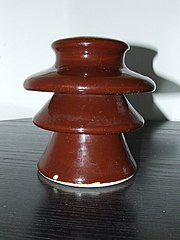
Line Insulator and their Specifications


    File:Ceramic electric insulator.jpg
Full resolution‎ (1,944 × 2,592 pixels, file size: 468 KB,     
                                 
                                Line Insulator and their Specifications
Transmission and distribution system leak overhead  line of the by chance  current can not flow, so that the line from the Earth, the Insulator is used for the line. Insulator important role in system operation.
Electricity Production and Distribution of the angular spread of the line biscuit, location, sag, span, etc., depending on the line of tension Insulator is used.
Insulator types:
A. Pin Insulator
B. Suspension Insulator
C. Strain Insulator
D. Shackle Insulator
E. Post Insulator
I. Egg or Guy Insulator
Insulator factors:
- Porcelain soil
- Glass
- Steatite
- Pyrex
Insulator material is better than the best in Porcelain soil. It is di-electric strength
 60 Kv /cm and the compressive & tensile strength 7000kg/cm² - 500kg/cm².

Properties of insulator materials:-
1. Cable should be strong enough to pull and weight labara.
2. High to provide the di-electric strength must be greater than the Relative permittivity.
3.Current flow may leak into the Earth, so it requires much more insulation resistance.
4.Flash over voltage, puncture voltage and high voltage ratio will be.
5. Insulator materials smooth, compact and flexible temperature must be uninfluenced.
6.Insulator must be authentic and have a good internal cresses.
7. It should be solid and impermeable, so that no one can enter inside the gas or fluid.
Use of different types of insulator:-
 
•. Pin Type Insulator: - It is usually LT Tangent line of the poll and the poll is a complete point angle. Distribution and transport of 33Kv.
 
•. Suspension Type Insulator: - usually 33Kv - to 230Kv, or it is used on a tangent Tower.
 
•. Shackle Type Insulator: - LT 400/30 V line to the terminal, and the more relevant point angular poll section is used.
 
•.  Strain type Insulator: - All the high pressure line, terminal, and the angular section is used to poll or Tower. The river crossing, railway crossing, the highway crossing, the drag of the Insulator is used.
 
•.Post Type Insulator: - It is much like a pin insulator. This Insulator create a massy shell. The outdoor sub-station HT Insulator  Busber used.
•. Egg or Guy Insulator: - Porcelain soil and the Insulator used this type of overhead lines. Line of the guy or the Sten - Sten was used so that when the cables were pulled poll is added over the ground so suddenly that the current leakage him may not come.
Insulator to test various methods of description: -
Insulator accuracy, consistency, and efficiency to be aware that  test is run, the Test of Insulator. Three of the test. Namely: -
1. Flash-over Tests
i. 50-Cycle dry flash-over test.
ii. 50-Cycle wet test for 30 Seconds.
iii. 50-Cycle flash-over test.
iv. Impulse frequency flash-over test.
2. Sample Tests or Performance Test:
i. Temperature Cycle test.
ii. Mechanical test (for Pin type insulator).
iii. Electromechanical test(for Suspension insulator)
iv. Puncture test.
v. Porosity test..
3. Routine test.
i. Proof load test.
ii. Corrosion test.
iii. High Voltage test.

শুক্রবার, ৩০ মার্চ, ২০১২

Conductive and conductive materials


undefined

undefined

                              Conductive and conductive materials.
Electric Power Transmission and Updated for the cable or overhead line distribution may be applied to both systems. The installment cost, considering the remote area of ​​all protected from the load center line insulation Power Transmission priority given to the overhead line.
Updated some of the accomplishments and benefits of overhead cabals very difficult to know. Transmission and distribution some kinds conductor without being used, namely: -
• Copper
• Aluminium.
• steel cored alumumium or A.C.S.R.
• Galvanized steel conductor
In addition, there are also such as phosphorous, bronze, copper clad, cadmium copper  etc.
Materials conductor properties: -
• High power Conductive  be prevented, which is relatively low.
• mechanical stress will be tensile strength should be high enough.
• It may be difficult and flexible. Should not be brittle.
• High short circuit produced by the additional heat that must be high melting point may be facing.
• the air pressure and the wire size should have sag  sustainable levels.
• If the conductive material is black.
• Humidity and moisture and rust proof  must be required.
• The sale will be sustainable and scraps.
But more than-
              Specific resistance.
              Specific weight.
              Temperature co-efficient of resistances.
              Young’s modulus.
              Ultimate tensile strength.
Copper, Aluminium, A.C.S.R. Comparative characteristics of cable: -
1.Copper: -
• Hard-drain copper conductor tensile strength too.
• It is less lustrous than conductive. So Support on the low pressure.
• Life span  much more.
• The weight of more than Aluminium.
2. Aluminium: -
• Lighter weight and price are cheaper than copper.
• copper and less than conductive someone’s resistance  1.7 times more fat and pecan difficult.
• Short circuit in the cable melting point less likely to have lost.
• Copper or A.C.S.R. tension bearing capacity of less than.
• provides a high voltage power produced in corona loser less than copper.
3. A.C.S.R (Aluminium conductor with steel Re-inforcedment): -
• This is relatively thick compared to other cable resistance the same.
Corona loss is less than the bodies. However, strong support is needed for a particular Span.
• Weight of tensile more strength.
• Sag less use of long span. The tower height is reduced proportionally.
4. Galvanized steel conductor: -
• The conductive less.
• Internal reactance more.
• Current and Hystersis Loss for more than Eddy current.
• wet weather rust on the wire. This cable is not used.
             

N.B:- Please do not forget to comment…

বুধবার, ৭ মার্চ, ২০১২

Head Over to Electric Line Support


Electric power of the conductive wire through the production center to be a long long way in 250 k.m. than high way patrol at the receiver end of the back, the only vehicles on-line support. Transport and variability, the location of the line to support it wood, concrete, or steel towers may be.
 Main components part of the overhead line:
1. Support:- Pole, Tower, etc., which depends on the size and height of the processing voltage. Safe distance from the ground up Supports conductor hold. Generally, the wood in the poll - Type I - Type-H - the type. Steel poll in tubular type, rail poll, etc. role steel joint. Poll of the concrete R.C.C. Poll, P.C.C. Use the poll. And latish steel tower. Wooden poll for the L.T. Distribution   line 400 V / 300 V are used to 11KV line. This is very useful for distance  up to

50 m span. Polls are around 6m-15m. Steel poll up to the L.T. line 11 KV -33KV line. A long span of 160 m up to 132 KV transmission line for the rest of the type used in the poll. Support line is replaced by criteria: - 
a. High mechanical stress bearing capacity will be, 
b. will be much cheaper price, maintenance costs will be lower,
c. and lighter weight will be error free, 
d. will be the long-standing, should be interesting things to see.
2. Cross - arm and clamp:- angle sections of steel or wood with a cross bolt nuts arms poll of the head is blocked. Cross - the arm with the clasp.
3. Insulator:- china or glass of varying voltage generated insulators  behead the systems, pin type , shackle or spool insulator, strain, suspension insulator , Egg or guy insulator  etc. are of various types. It is generally conductor - to - conductor, conductor - to - Earth insulation provide.
4. Guys and stays:- Stays poll over his use of the guys and the Insulator.
5. Conductor:- copper, Aluminium, or A.C.S.R Through a line of electric coductor power one place to another must be in place.
6.  Lighting  arrestors:- Lightning induced additional voltage  to protect the line.
7.  Fuses and Isolating switches: They are different parts of the overhead system, the network can be isolated if necessary.
8. Continuous earth wire:- Tower or the poll is over the top of the line along the entire Earth trait. The unusual circumstances created by the additional voltage  Discharge line to protect the soil easily.
9. Guard wire:- When a power line, telephone or telegraph line crossing, and then find the line that connects the top and bottom of the Earth Wire is used to guard.
10. Bird guards:- it is created on the side of the saw teeth as long ebonite basest plate, which is a cross - is prevented in the presence of arm insulator. The birds of hokier cross - in the arm and conductor Flash - Over in the  out .
11. Vibration damper:- vibration damper  dimple shape in the presence of these lines connect to the poll, that tremble down the line. The air flow through the conductor is conductor vibration, the vibration is. The pressure on the conductor in the conductor can be read off tear. The best way to protect against damage from vibration induced arms rod is used. Bates is one of the Stock Bridge damper .The shaking intensity is used to prevent damper betas.
12. Jumpers:- jumpers connection is connected via the two conductor. Nevertheless, as part of the phase plate, Danger plate, Barbed wire, Cradle guard. Etc.


Q. What is the cradle guard ? Where is the use?
Ans:- Head over to his line - where the roads, rail lines, or building on the trail, there are safety devices used not only for safety. After his off tear it down at all, so that people do not readit, so that the bottom line is earthed cradle Guard.
Telecommunication lines in the repair and look after all the time. The line between Telecommunication riper  security guard earthed cradle guard used.